El Niu: Andorra’s Pioneering Passivhaus Plus Certified Building
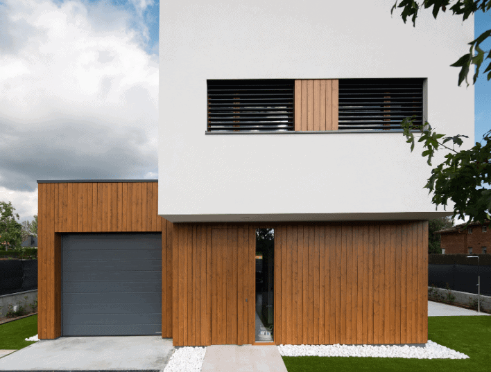
In the heart of Andorra, Europe’s 6th smallest state, a groundbreaking architectural marvel named “El Niu” is redefining sustainable living. Meaning “The Nest” in Catalan, El Niu is a testament to innovative design, energy efficiency, and environmental consciousness.
El Niu: Andorra’s Pioneering Passivhaus Plus Certified Building
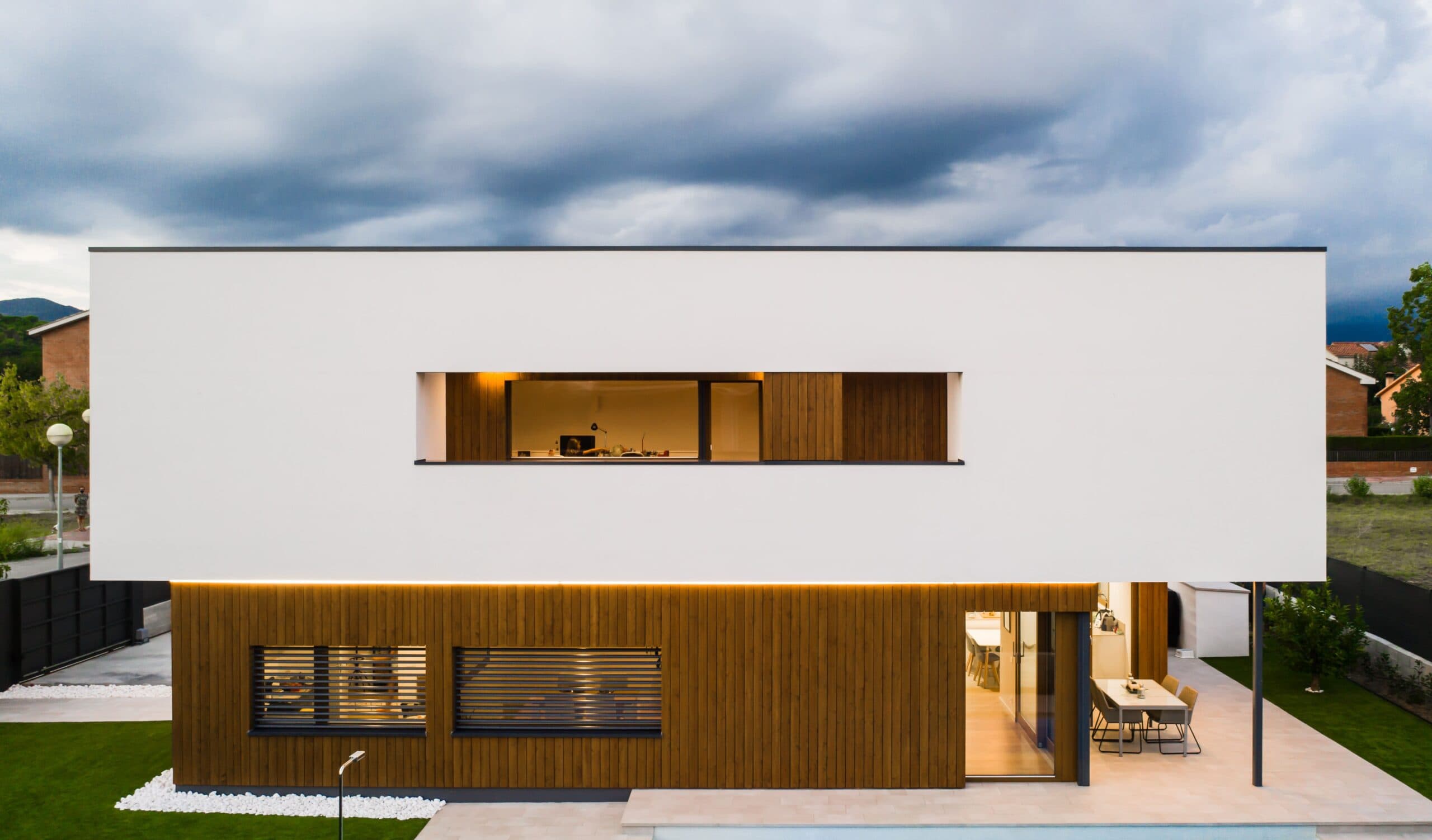
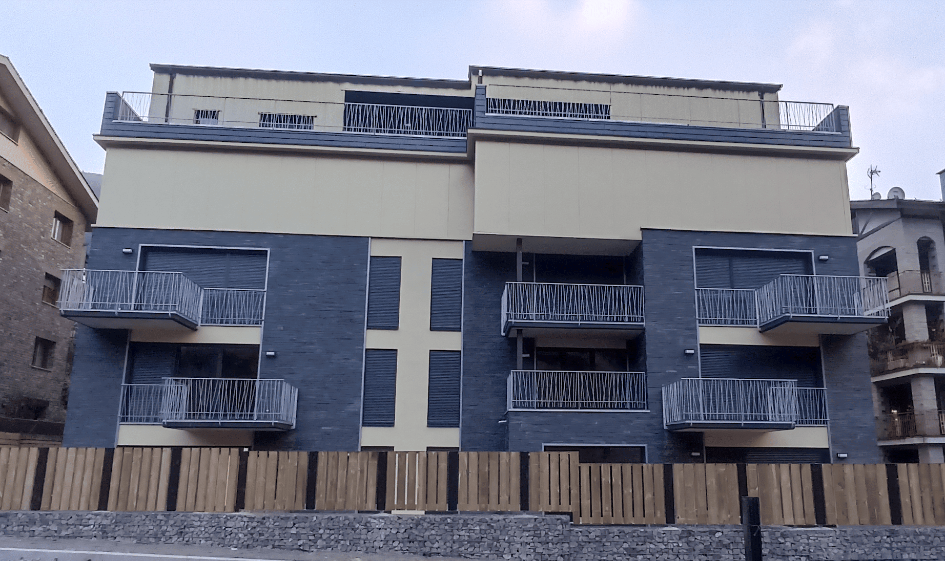
El Niu is a testament to innovative design, energy efficiency, and environmental consciousness
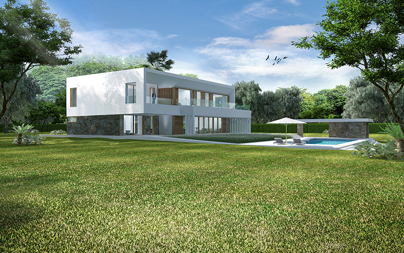
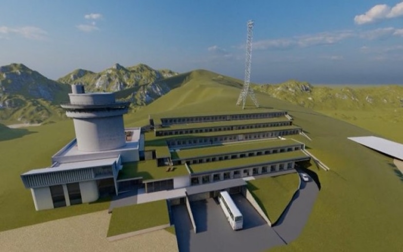
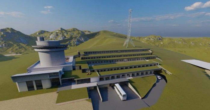
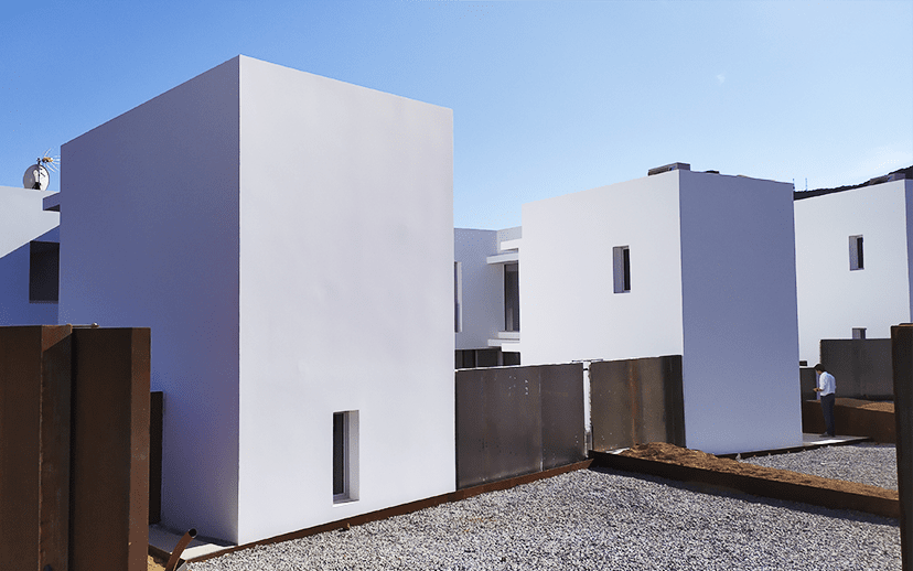
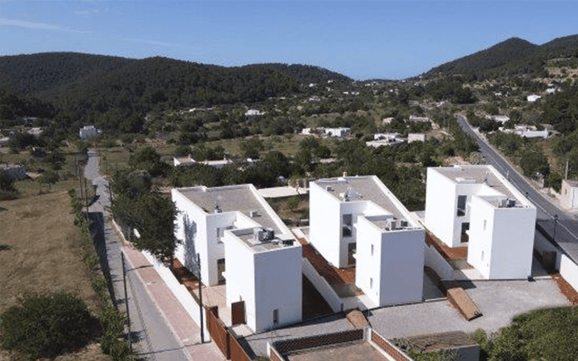
Nestled 1275 meters above sea level, El Niu accommodates 11 dwelling units across four floors
In the heart of Andorra, Europe’s 6th smallest state, a groundbreaking architectural marvel named “El Niu” is redefining sustainable living. Meaning “The Nest” in Catalan, El Niu is a testament to innovative design, energy efficiency, and environmental consciousness.
Passivhaus Plus Certification
El Niu proudly stands as Andorra’s first multi-residential building to achieve the prestigious Passivhaus Plus certification. This accolade, awarded by Passivhaus Certifier Oliver Style of Praxis Resilient Buildings, is a testament to the collaborative efforts of the development team, including Lluis Lopez Castro of Propietats y Gestió and architect Antoni Martí.
Bernabé Rodríguez’s expertise in mechanical and electrical services engineering, coupled with Pere Marcé Coma’s airtightness Blower Door tests, played important roles in attaining this esteemed certification. Months of dedication and meticulous attention to detail, together with countless rolls of airtight tape, have marked a transformative milestone for Andorra’s architectural landscape.
High Altitude, High Efficiency
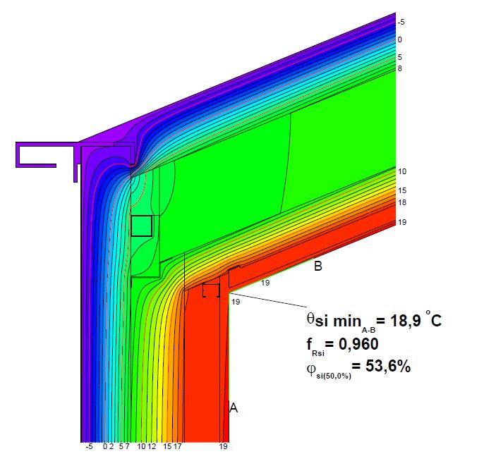
Nestled 1275 meters above sea level, El Niu accommodates 11 dwelling units across four floors. Facing challenging weather conditions, with temperatures dropping below -10 ºC and winds reaching up to 40 km/h in the depths of winter, El Niu will ensure residents remain warm and cozy. This is achieved through a combination of high levels of insulation, thermal bridge-free construction, high-performance windows, excellent airtightness, and a mechanical ventilation system with heat recovery, all contributing to create an impeccable thermal envelope.
Pioneering Heating and Hot Water Solutions
El Niu sets a new standard in energy-efficient heating and hot water systems with the use of Pichler PKOM 4 compact heat pump units for each apartment, supplied by Orkli. These Passivhaus certified all-in-one units provide mechanical ventilation with heat recovery, heating, cooling, and hot water generation. Notably, they eliminate the need for large and energy-intensive centralised heating and hot water systems, addressing sustainability concerns by minimizing energy consumption, while reducing winter heat losses and summer heat gains that can be perilous for overheating.
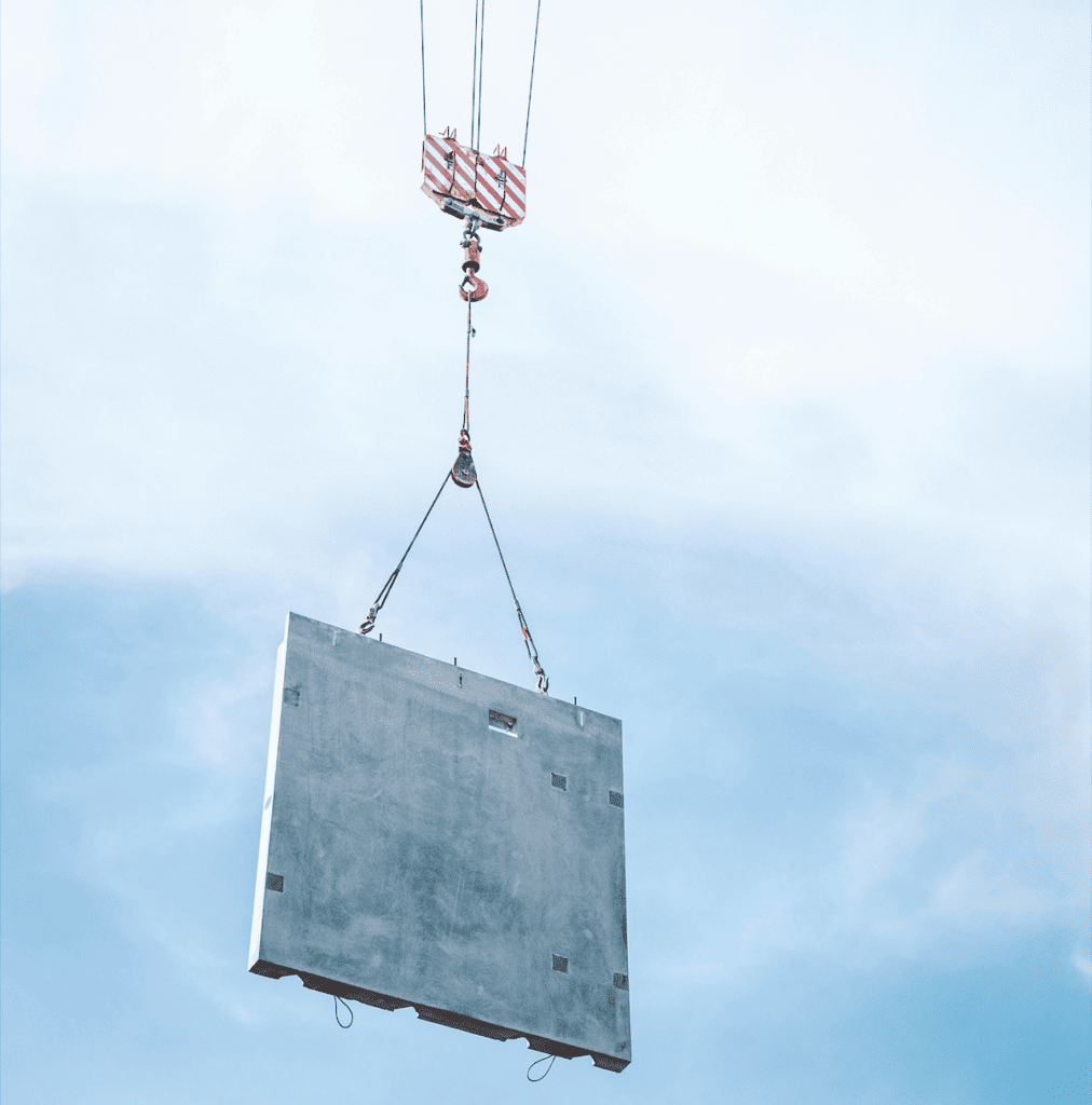
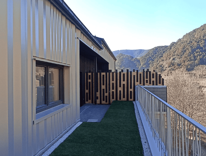
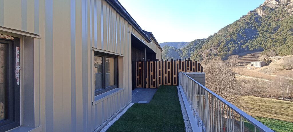
Innovative lightweight façade systems
The outer walls of the building consist of two distinct light weight steel frame systems: the Passivhaus certified Passivhaus External Wall System by Knauf Insulation, and the Archisol and Promisol systems by Arcelor Mittal. The Passivhaus certification of the Knauf Insulation system guarantees thermal bridge-free construction and added an extra layer of quality assurance. In addition, Knauf insulation used throughout the building is made from more than 80% recycled glass and incorporates the bio-based E-Technology binder, free from added phenols and formaldehydes, protecting both the workers on site and future occupants from harmful emissions.
Airtightness Excellence
Xavier Rodriguez from SIGA provided airtightness technical support, tapes, and membranes. Thanks to the meticulous work of Lluis Lopez and his team, they met the stringent Blower Door test requirement of n50 ≤ 0.6 ach, guaranteeing a draught-free, high-comfort living experience for El Niu’s occupants, irrespective of the external weather conditions.
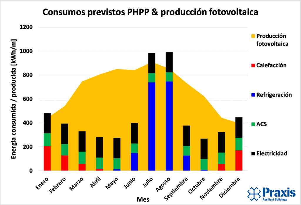
Solar Power: The Green Finale
El Niu’s commitment to sustainability culminates in a 37.7 kWp solar PV array projected to generate 91% of the building’s energy consumption. This transformative addition turns El Niu into a nearly net-zero energy powerhouse, using approximately 71% less energy than pre-2010 buildings in Andorra. Impressively, it achieves this while emitting only 5976 kg of CO2eq per annum, contributing significantly to the reduction of the building’s carbon footprint.
In conclusion, El Niu represents a paradigm shift in Andorran residential construction, blending architectural innovation with environmental responsibility. As a Passivhaus Plus certified building, it not only provides a haven for its occupants but also sets a precedent for sustainable living in Andorra and beyond. El Niu is more than a nest: it’s a beacon of hope for a greener, more energy-efficient future.
For more technical information, check out our project data sheet here and in the International Passivhaus Database