Passivhaus in the Mediterranean? Strategies for keeping cool in a Passivhaus on the beach
A significant rise in temperatures is expected in the Mediterranean area in the coming years. Therefore, identifying and implementing effective strategies to reduce indoor temperatures in buildings and reduce the need for air conditioning is increasingly important.
Passivhaus in the Mediterranean? Strategies for keeping cool in a Passivhaus on the beach
According to the climate modelling presented in the study “Study on Climate Change and Energy in the Mediterranean” carried out by the European Investment Bank, countries in the Mediterranean basin will experience an increase of between 3ºC – 6ºC in average temperatures between the period 2070-2099, based on the 1961-1990 period.

The need to tackle overheating is addressed directly in the European Directive 2010/31/EU for nearly zero energy buildings (nZEB), which states the following: “Priority should be given to strategies that improve the thermal performance of buildings in the summer. To this end, measures should be promoted to prevent overheating, such as shading and sufficient thermal inertia in the construction of buildings, as well as to improve and apply passive cooling techniques (…)” [2]. This article presents the strategies used to improve the thermal performance in summer of a passive house in a Mediterranean climate.
Caste study: “Esencia Mediterránea”…passive house on the beach
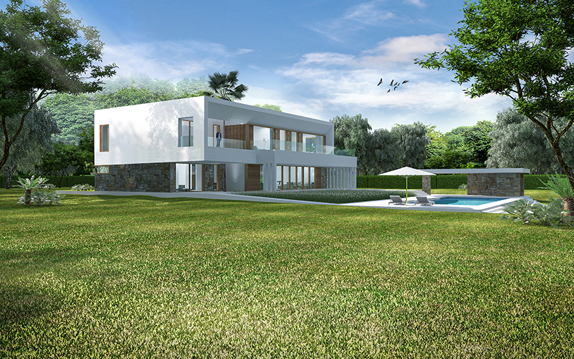
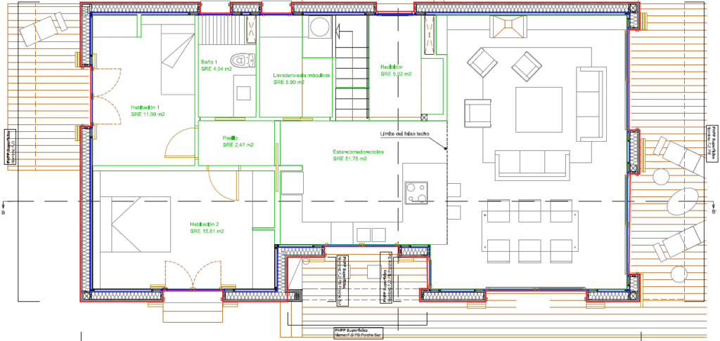
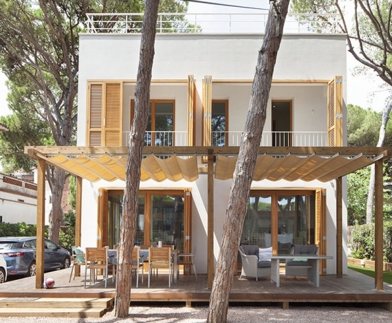
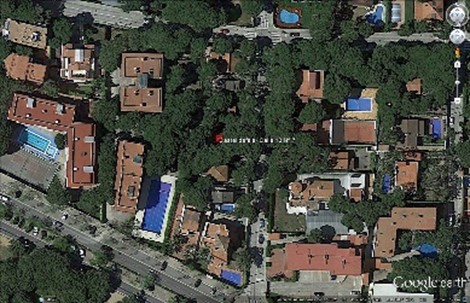
The home, “Esencia Mediterránea,” has a useful area of 173m2, over two floors, located about 50 meters from the beach, 3 m above sea level (Figure 2, Figure 3, Figure 4) It has an architectural design very much in line with the Mediterranean vernacular tradition, was designed by Guillermo and Iciar Sen, built by House Habitat, and is Passivhaus certified.


The project team:
- Architects: Guillermo Sen, Iciar Sen
- Technical Architect: Javier García Garrido – Garcia & Sala Arquitectes
- Builder: Pere Linares – House Habitat
- PHPP & building physics: Oliver Style, Bega Clavero
- HVAC design: Vicenç Fulcarà – Progetic
- Passivhaus and Blower Door Certification: Micheel Wassouf, Martín Amado – Energiehaus
Passive cooling strategies
Many of the strategies used to improve the summer performance of the home are rooted in traditional Mediterranean vernacular architecture and combined with modern solutions. For the thermal analysis presented here, a PHPP model of the house was prepared to meet the minimum requirements of the Spanish Building Code (CTE). Subsequently, the impact of each strategy on cooling demand is presented, until the limiting cooling demand value required by the Passivhaus standard is achieved.
Shading analysis
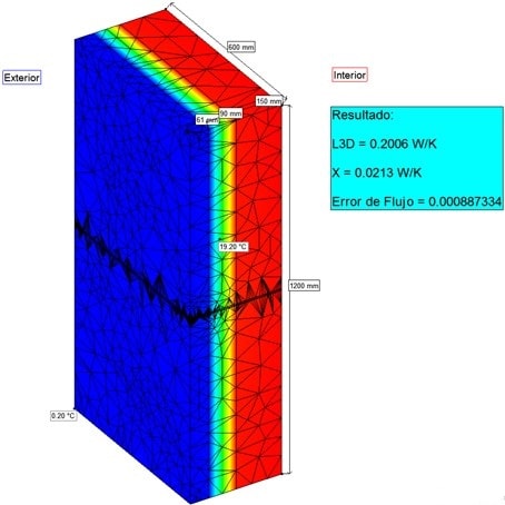
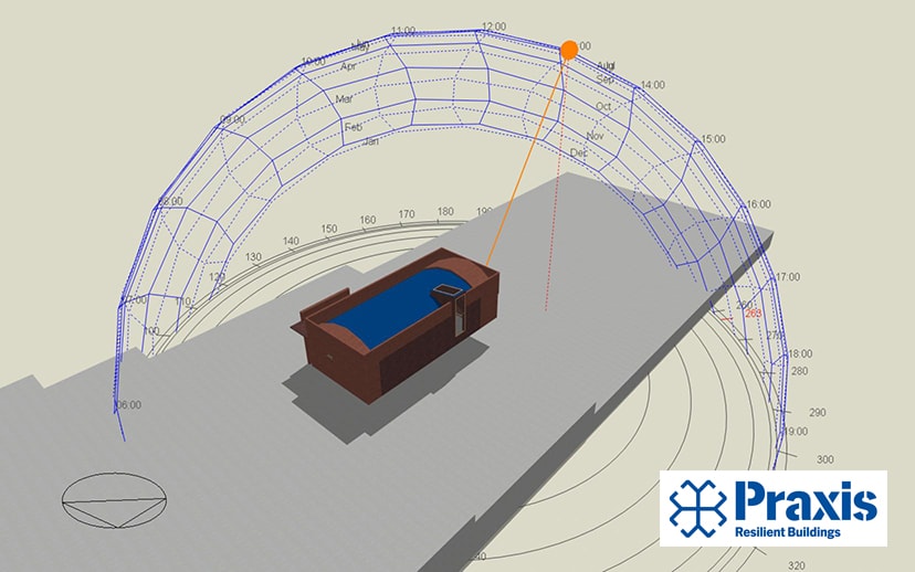
In order to be able to more accurately check the impact of design strategies for the summer, a shadow study was carried out with the DesignBuilder – EnergyPlus thermo-dynamic tool(Figure 7, Figure 8, Figure 9). The results were used to calculated shading reduction factors for each window, that were later introduced in the PHPP shading tab.


Thermal inertia and natural night ventilation
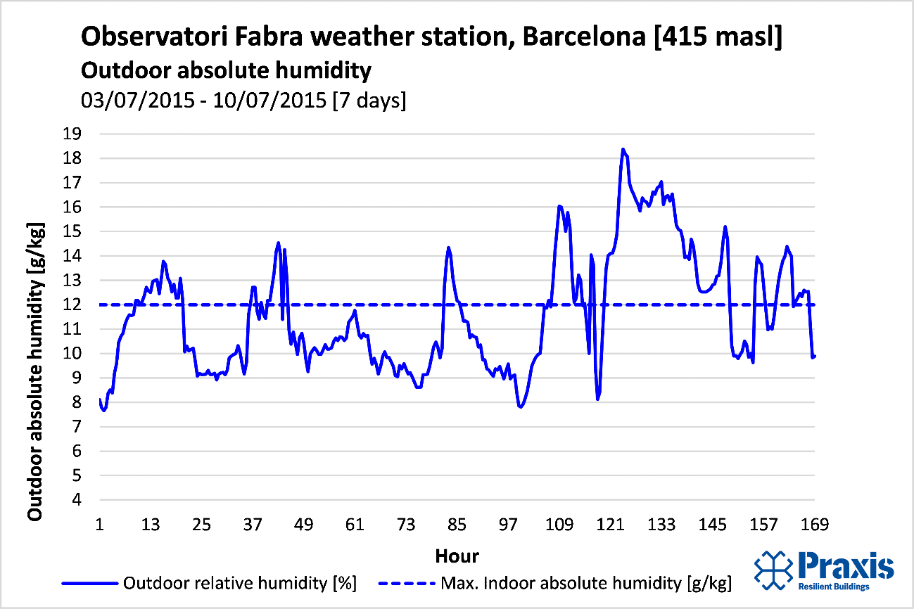
Combining thermal mass with natural cross ventilation is a key Mediterranean passive cooling strategy. Cooling power is logically limited when minimum night-time temperatures are not sufficiently low (< 18 ºC), so the strategy tends to work best in climates that are inland and at a higher altitude than coastal areas. While lightweight Passive Houses in warm climates have shown good summer performance [3, 4], some thermal inertia, in combination with night ventilation, clearly helps to modulate indoor temperatures and dissipate heat, improving comfort conditions and reducing cooling energy consumption. The house in question was built with a lightweight timber system – inherently low inertia. To incorporate some mass and enhance the effect of natural night ventilation, a 5 cm of mortar layer with ceramic floor tiles were installed on the floors of both floors, providing a specific capacity of 85 Wh/K·m2 inertia (compared to a very light building of 60 Wh/K·m2). With tilt-and-turn windows partially opened at night, a minimum night ventilation air change rate of 0,8/h was calculated with the PHPP tool, provided by simple, cross and stack effect ventilation.
Reflective surfaces: walls and roofs
White painted walls and roofs are another feature of traditional Mediterranean architecture. The house has a white silicate mortar render, with a white roof, both with a solar absorption factor of α = 40 % (black α = 95 %). This helps to reflect more solar radiation and reduces transmission heat gains to the interior of the house.
Shading devices and solar control
Solar gains are reduced with balconies set back from the façade, exterior shading devices, and solar control glazing with a solar factor of 36%.
Thermal insulation
Thermal insulation reduces transmission heat gains, especially through roofs. It is important to find a balance between the insulation thicknesses needed for winter and summer, since an excessive thickness of insulation can in some cases prevent heat dissipation at night in the summer. On the ground floor, 15 cm of wood fibre insulation was used, U = 0.264 W/m2·K. On external walls, 20 cm of wood fibre insulation was installed between the timber structure with 6 cm of external high-density wood fibre insulation, U = 0,158 W/m2·K. The roof has 26 cm of wood fibre insulation, for a U = 0,152 W/m2·K
Air infiltration
Reducing air ex/infiltration is a strategy that comes from cold and temperate climates, where the priority is to reduce winter heat losses, when there can often be an indoor-outdoor ΔT of 30 ºC. Outdoor air temperatures would have to be 55 ºC to have the same ΔT in summer. However, reducing air infiltrations in coastal Mediterranean climates with high humidity can help reduce latent cooling loads when active cooling is on and windows are shut. In the case study home presented here, reducing air infiltration from n50 = 5 ach (a typical value for newly built homes) to n50 = 0.4 ach, the latent cooling load is reduced by 39% and the latent cooling demand by 7%.
Mechanical ventilation with heat and moisture recovery (enthalpy) + automatic bypass in summer
Mechanical ventilation with heat recovery (MVHR) is another solution that originated in central and northern Europe. Does it work in a Mediterranean summer? When outdoor temperatures rise above the indoor comfort temperature (> 25 ºC), users in air-conditioned Mediterranean homes typically close windows and turn on the cooling system, with negative consequences for indoor air quality. A mechanical ventilation system with heat recovery and automatic summer bypass, ensures constant air change and high air quality. When Tout > Tint the heat recovery unit reduces the temperature of the inlet air, shown in Figure 10, where heat recovery reduces the temperature of incoming air from 35.5 ºC to 29.5 ºC:

When Tout < Tint the automatic bypass opens, providing free cooling and bypassing heat recovery. Additionally, an enthalpy unit reduces the amount of water vapor that enters the house in summer when the absolute humidity of the outdoor air is greater than the extract air (which is often the case in warm humid climates in homes with air conditioning / dehumidification). When the air conditioning is off, users can of course open windows at any point.
Discussion and conclusions
Figure 11 shows the PHPP simulation results for each of the strategies described above. The reduction in cooling demands from insulation on the roof is less than on the walls – a result that seems surprising. This is due to shading from the tree canopy, which means the reduction is less than in the walls. The results show that the combination of all strategies is greater than the sum of individual strategies. Cooling demand is reduced from 33 kWh/m2·a with the CTE code-compliant building, to 18 kWh/m2·a, meeting the requirements for the Passivhaus certification in a Barcelona climate.

Combining traditional Mediterranean passive cooling strategies with solutions included in the Passivhaus standard, the summer performance of buildings can be improved with a reduced need for air conditioning. “Stress testing” your design with a tool such as PHPP in the early stages of the project is essential, and post-construction monitoring and evaluation is highly recommended to learn from mistakes and improve.
References
[1] Somot, S. (2005), “Modélisation climatique du bassin Méditerranéen: Variabilité et scénarios de changement climatique.” Thése de Doctorat, Université Toulouse III-Paul Sabatier. UFR Sciences de la Vie et de la Terre. pp 347. Toulouse, Francia, 2005. [2] Parlamento Europeo (2010), “Directiva 2010/31/UE del Parlamento Europeo y del Consejo, de 19 de mayo de 2010, relativa a la eficiencia energética de los edificios (refundición)”. Parlamento y Consejo Europeo, Bruselas, 2010. [3] Wassouf, M. (2015), “Comfort and Passive House in the Mediterranean summer – monitorization of 2 detached homes in Spain Barcelona”, 19th IPHC, Leipizig, Alemania. [4] Oliver Style (2016), “Measured performance of a lightweight straw bale passive house in a Mediterranean heat wave”. 20th International Passivhaus Conference, Darmstadt, Alemania.